Grundfos Motor Wiring Diagram
Wiring diagrams 8. Disposal 2 3 3 3 3 4 4 4 5 9 Warning Prior to installation, read these installation and operating instructions. Installation and operation must comply with local regulations and accepted codes of good practice. This booklet should be left with the owner of the pump for future reference and information regarding its operation.

Grundfos Pump Wiring Diagram Easy Wiring
Get help for your installing and operating needs. Look for how to guides here to find quick and easy guidance and support for all phases of your project. Discover a range of online engineering, installation and operation tools and up-to-date pump design information that can assist you in your work today, and help you work smarter over the long run.

Grundfos Pump Wiring Diagram
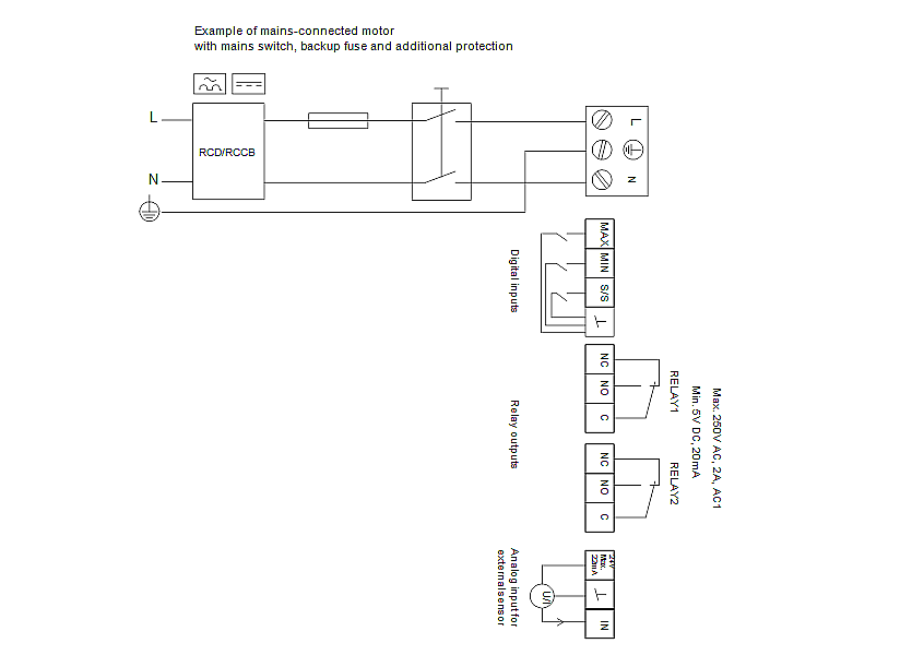
SmartFlo wiring diagram Terminal Function 91 (L1) Single-phase supply 92 (L2) 95/99 (PE) Ground connection 4. Connect the motor. MOTOR PUMP (U) (V) (W) (PE) 96 98 97 99 Yellow Red Black Motor leads 107 Motor connection wiring diagram 5. Plug the terminal strip.. For Grundfos 230 V 3-phase motors, the direction of motor rotation is correct in.
Grundfos Motor Wiring Diagram
See how a Grundfos service specialist introduces Grundfos KPL Axial Flow Pump for Flood Control pump and find out what the job requires and how it is perform.
Grundfos Motor Wiring Diagram Weavemed
Fig. 2 Wiring diagram B for single-phase pumps TM06 4453 2315 Red Blue Black NL Red Capacitor Blue Black Capacitor TM06 4451 2315 White Red W2 W1 V2 U1 Blue Blue Capacitor Brown Ground Motor protection. Grundfos NS pumps are centrifugal pumps designed for lifting water in domestic, industrial and agricultural installations.
Grundfos Circulating Pump Wiring Diagram Wiring Diagram
How to guide How to find installation and operation manuals online Find all the pump manuals and pump installation guides you need to make your system run to the best of its capabilities. Learn how you can find pump manuals in this video. Get the most out of your system

Grundfos Pump Wiring Diagram
Step 1: Go to Grundfos Product Center Once you enter Grundfos Product Center, you will see a menu with four coloured categories at the top. Select 'Catalogue'. Step 2: Find your product Once you're in the 'Catalogue' section, select either 'Pump designs', 'Applications' or 'Product families', depending on what you need. Select your product.
Grundfos Pump Wiring Diagram
Products manufactured by GRUNDFOS PUMPS CORPORATION (Grundfos) are warranted to the original user only to be free of defects in material and workmanship for a period of 24 months. 9.1 Wiring diagrams 11 9.2 Start and stop levels 11 9.3 Pump controllers 12 9.4 Thermal switches 12 10. Start-up 12 10.1 General start-up procedure 12
[35+] Grundfos Condensate Pump Wiring Diagram, Grundfos Pump Wiring Diagram
Step 1: Search by product name or number You can type in the product name and press search to find matches. Or if you have the product number, you can search by that as well. Step 2: Select your product and view information

Grundfos Pump Wiring Diagram Easy Wiring
These installation and operating instructions describe Grundfos ALPHA2 26-99 circulator pumps. Sections 1-4 give the information necessary to be able to unpack, install and start up the product in a safe way. Sections 5-9 give important information about the product, as well as information on service, fault finding and disposal of the product.

Grundfos Pump Wiring Diagram Free Wiring Diagram
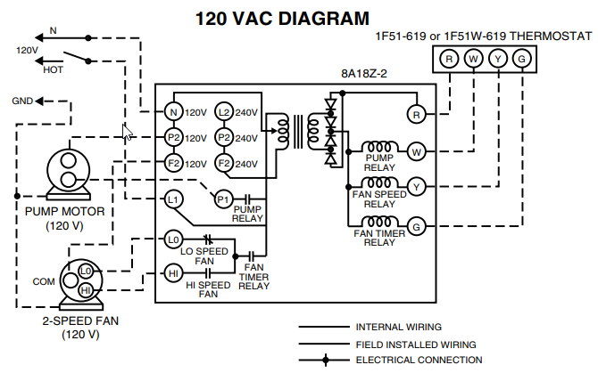
The wiring diagram is located in the terminal box cover. The terminal box of single-speed motors normally contains six winding terminals and at least one earth. pump. Grundfos motors, types MG 71 and MG 80 as well as MG 90 (1.5 kW, 2-pole), for supply voltages up to and including 440 V
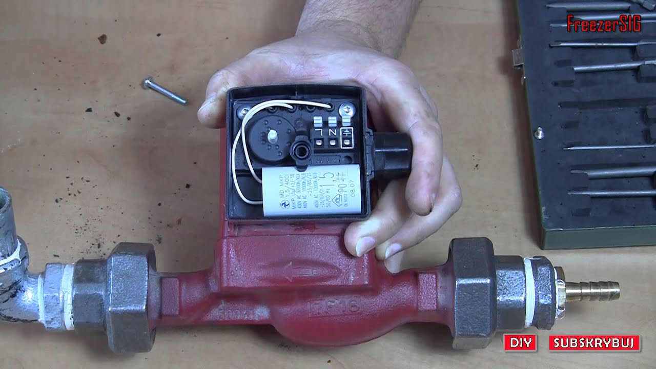
How to setup wire connection on Grundfos UPS2 pump YouTube
If not, replace the pump, or contains too much air. call GRUNDFOS SERVICE for assistance. Replace the pump, or call GRUNDFOS SERVICE for Internal fault in the pump electronics. assistance. Supply voltage to the pump too high. Page 19: Technical Data 0.145 psi / 0.01 bar / 0.001 MPa per 328 ft (100 m) altitude. 1 x 115 V ± 10 %, 50/60 Hz, PE.

Grundfos Pump Wiring Diagram Free Wiring Diagram
5.1.1 Single speed and multi-speed pump wiring 1. Insert black conductor into terminal "L" position. 2. Insert white conductor into terminal "N" position. 3. Insert grounding conductor into terminal " " position. Fig. 3 Wiring diagram for all 115 V and 230 V single-speed pumps Fig. 4 Wiring diagram for 115 V and 230 V multi-speed pumps*

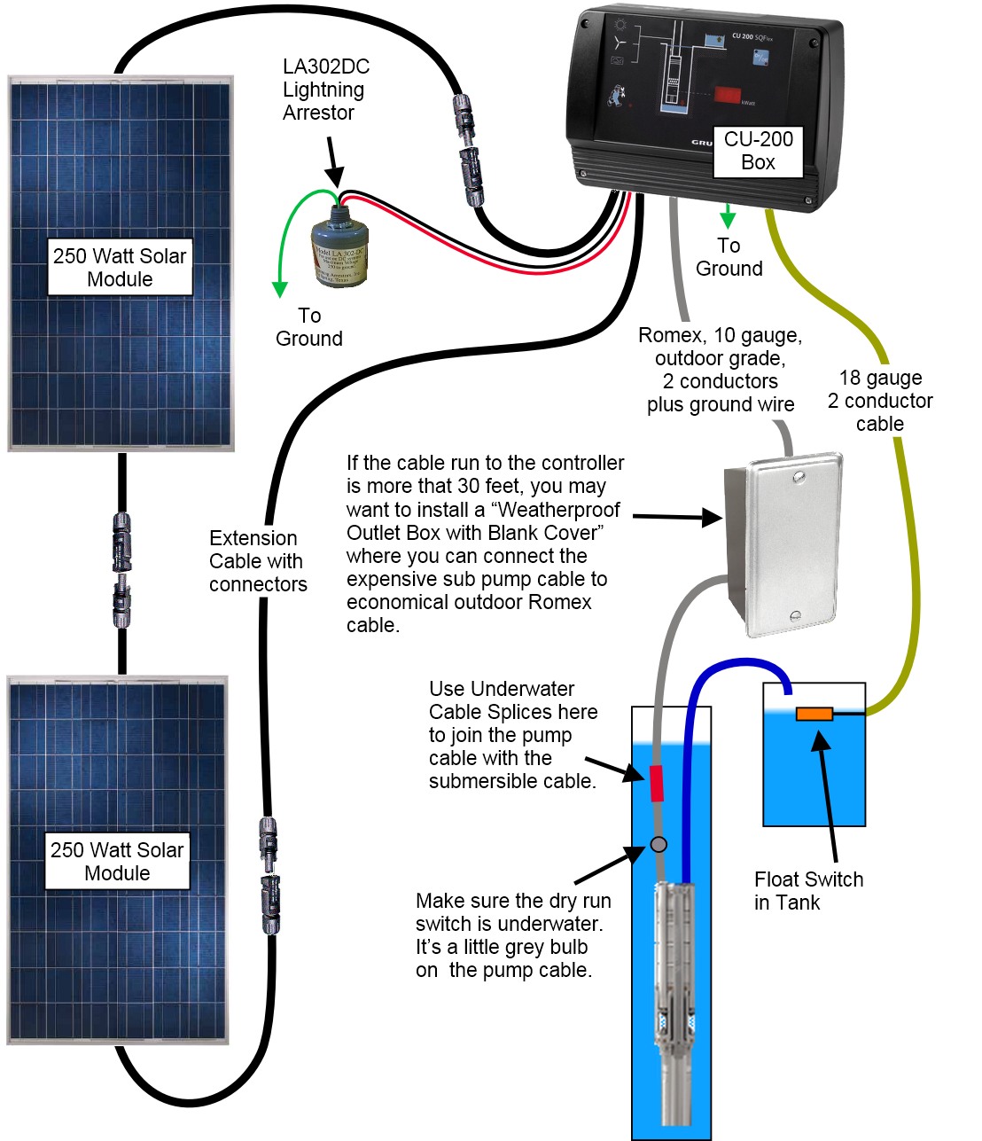
Grundfos Cu 200 Wiring Diagram
8.1 Wiring diagrams 19 8.2 Pump controllers 20 8.3 Thermal switch, Pt1000 and thermistor 20 8.4 WIO sensor (water-in-oil sensor) 21. Pump type Grundfos sewage/wastewater pumps 1 V Impeller type Single-channel impeller Free-flow impeller (SuperVortex) 80 Pump passage Maximum solids size [mm] 80

Grundfos Pump Wiring Diagram
Products manufactured by GRUNDFOS PUMPS CORPORATION (Grundfos) are warranted to the original user only to be free of defects in material and workmanship for a period of 24 months. 5.3 Connection diagram 11 5.4 Connection to external controllers 11 5.5 Input/output communication 11 5.6 Priority of settings 14 6. First start-up 15

Grundfos Water Pump Wiring Diagram The Human Tower
It controls various aspects such as pump start/stop, motor protection, fault monitoring, and system status indication. This panel plays a vital role in ensuring the longevity and reliability of Grundfos pumps. Understanding the wiring diagram of a Grundfos Pump Control Panel is essential for proper installation, maintenance, and troubleshooting.
